
Attenuated total reflectance-FTIR spectroscopy (ATR-FTIR) is a simple, label free, non-invasive, non-destructive analytical technique that can characterise the biochemical profile of a sample. It can be used to interrogate a wide variety of biofluids.
The ATR TOOL consists of an initial character TS, followed by a maximum of 32 additional characters. These characters encode communication parameters and protocols that the card proposes to use for the remainder of the session until the next reset.
ATR Characters
The ATR Characters are a string of characters output by a contact Smart Card conforming to ISO/IEC 7816 standards following an electrical reset of the chip by a card reader. They provide information to the terminal about how to communicate with the card for the remainder of the session.
TS encodes the value of the first byte, which may be either a direct or inverse conversion (‘3B’ or ‘3F’). The next 8 bits are numbered from low to high, and their values are noted as 0 or 1, regardless of the chronological order and electrical representation defined by TS.
TA1
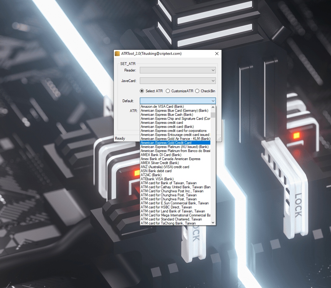
An ATR (answer to reset) is a message output by a contact Smart Card conforming to ISO/IEC 7816 standards, following electrical reset of the card’s chip by a reader.
It conveys information about the communication parameters proposed by the card, and the card’s nature and state. It also contains a check byte TCK.
TA2
The first character of the ATR sequence, designated TS, synchronizes information and defines the polarity of all subsequent characters. TS comprises a start bit at L state, 8 data bits, and a parity bit.
It also encodes the Initial ETU value during ATR, and will continue to use it during subsequent exchanges unless changed outside of the basic ATR. This value is defined by the ratio Fi/Di (fmax).
TB1
TB1 encodes PI1 in range [5..25]; it indicates whether the C6 contact used for VPP is connected in the card. Alternatively, it suggests that the VPP is not used and that the card uses an external programming voltage (VPP).
The high 5 bits of TB1 (5th MSbit to 1st LSbit) encode TC1, which determines the extra guard time to be added between consecutive characters sent from the terminal to the smart card. The value ‘FF’ is the minimum, while ’00’ is the maximum.
TC1
The TC1 character (as in Table 2) encodes a value of N that determines the additional guard time to be added between consecutive characters sent from a terminal to a card. N may be a non-negative number between 0 and 255.
It can also be an integer representing a number of ETUs to be reduced during T=0 protocol communication; or it can be a number of ETUs to be increased during T=1 communication. Depending on its value, the SMCHGUARD register will be programmed accordingly.
TC2
TC2, if present, encodes the Guard Time, varying from a baseline of 12 ETU (corresponding to 1 start bit, 8 data bits, and 1 parity bit). This value is used by the reader to decide the minimum interval between the leading edges of two characters sent by interface in opposite directions.
TA2, if present, also encodes the Command APDU. The Command APDU consists of a required 4-byte header followed by an optional body of variable length that can contain data.
TA3
The TA3 character if present, codes the card’s information field size (IFSC). It is the max. number of blocks that a terminal can send to the card.
The TS byte encodes the convention used for the ATR’s encoding, and further communications until the next reset. Bits with logic value ‘1’ are transferred as High voltage (H) and bits with logic value ‘0’ as Low voltage (L).
TD1
Following an initial reset by the card, it responds with a series of characters known as the Answer to Reset (ATR), which establishes the protocol and bit timing conditions for subsequent communications.
Character TA2 encodes in its 4 low-order bits an integer T representing the transmission protocol required by the card. EMV prescribes that a card which does not T encoded in TA2 will be rejected.
TD2
TD2 encodes the protocol required for the card. The specific mode byte is also present and commands that the reader uses a specific mode.
In addition, TA2 is global if it exists, and commands that the reader uses negotiable mode if it does not. Earlier global bytes are not affected by TA2.
TA4
TA1 (if present), is global, and encodes fmax; the number of clock cycles per ETU that the card suggests using after ATR; expressed as the ratio Fi/Di.
In ISO/IEC 7816-3:1989, this was coded by a 4-bit notation of ‘D’ for Di; in EMV, ‘FI’. In either case, the lowest 4 bits of TA1 are encoded. The corresponding ‘1’ bits are then transferred as H or L (respectively high or low voltage on I/O) in direct or inverse convention defined by TS.
Comments are closed.